Altium Designer is an EDA software package used for implementing schematic PCB design FPGA and embedded software design as well as providing Mixed-Signal simulation and analog and digital circuit analysis. Users must have an Altium Account created by ITS. Altium designer 20 requirements.
Altium Designer 20 Requirements, It may be a good idea to setup a separate design rule for minimum clearance between polygon pours and trackspads for example 08mm to make it. If you are interested all the design documentation and Gerbers files produce in this course can be used to build your own PCB. It is developed and marketed by Altium Limited.
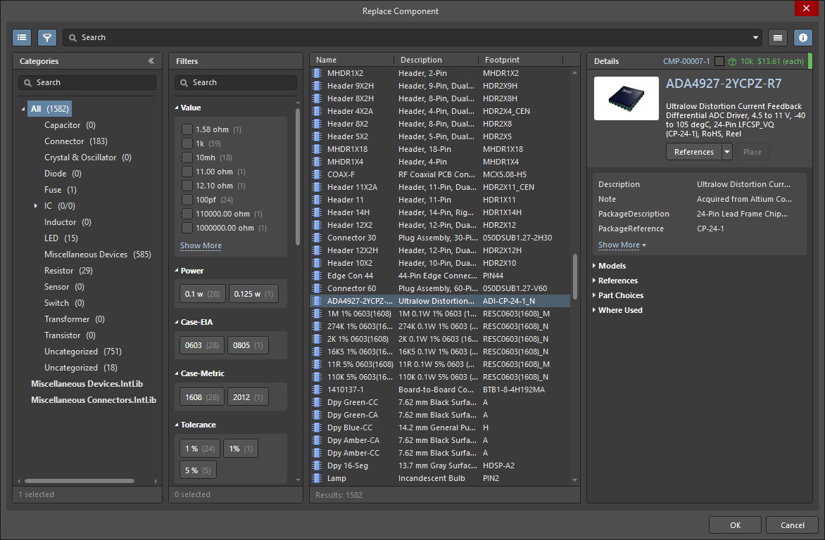 Replace Component Managed Altium Designer 21 User Manual Documentation From altium.com
One to pick the first copper feature and the next to pick the second. The Net Tie is a Component Type that allows PCB Engineers and Designers flexibility when Handling a Variety of Design Challenges. Now in this board design only one of the inner layers is being used for 750 volt routes. Key highlights New PCB connection drawing options New options have been implemented in the View Configurations dialog for Show All Connections In Single Layer Mode and Use Layer Colors For Connection Drawing.
Comprehensive Simulation Model Support.
This Paper Explores the Advantages to using Net Ties in Altium Designer to Join Multiple Nets shorts Into One Single Net at Very specific Locations in the PCB. One to pick the first copper feature and the next to pick the second. New in Altium Designer 21. In the case of the electrical clearance rule two queries are executed. Users can install Altium on their personal machines. By default the query is simply All which means that the design rule is applied to every object in the design.
Read another article:
 Source: altium.com
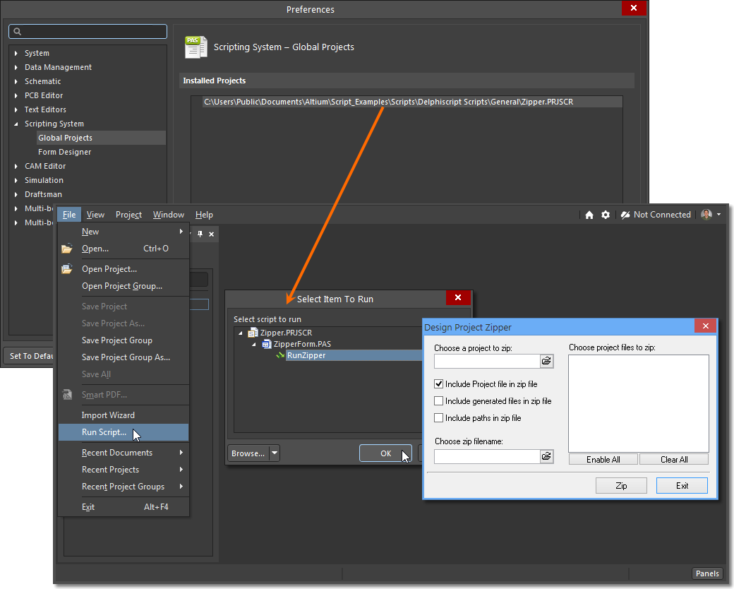
0214 Dec 28 2020. 0043 Dec 28 2020. Comprehensive Simulation Model Support. Monitor with at least 1680x1050 widescreen or 1600x1200 43 screen resolution. Running Scripts In Altium Designer Altium Designer 21 User Manual Documentation.
 Source: altium.com
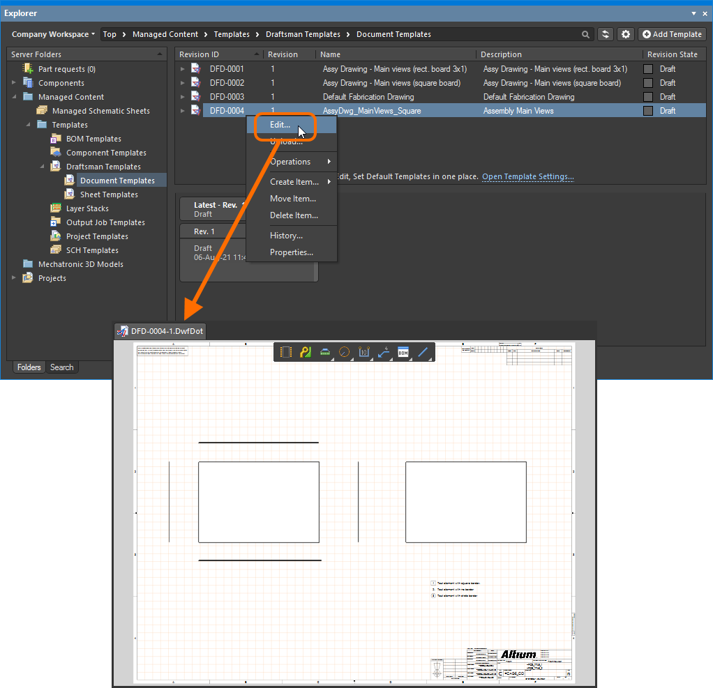
Recently we updated to Altium Designer 20. This Paper Explores the Advantages to using Net Ties in Altium Designer to Join Multiple Nets shorts Into One Single Net at Very specific Locations in the PCB. Including a schematic PCB module and an auto-router and differential pair routing features it supports track length tuning and 3D modeling. Altium Designer includes tools for all circuit. Designing With A Connected Workspace In Altium Designer Altium Designer 21 User Manual Documentation.
 Source: pinterest.com
Rigid-Flex Board Planning Mode. Start Your Free Trial. Design Rules and Constraints with Altium Designer 20. Second Object query is Not InNetClass 750Volts And OnMid Or OnMultiLayer Different Nets Only Minimum Clearance 40mil. Altium Designer Crack 21 5 1 With License Key Latest Vst Links.
 Source: eenewseurope.com
0133 Dec 28 2020. Now in this board design only one of the inner layers is being used for 750 volt routes. Monitor with at least 1680x1050 widescreen or 1600x1200 43 screen resolution. 0133 Dec 28 2020. Altium Rejects 4bn Takeover Offer.
 Source: resources.altium.com
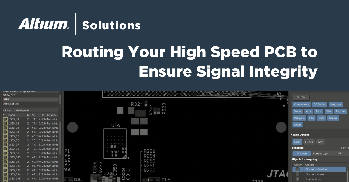
10GB hard disk space Install User Files Graphics card supporting DirectX 10 or better such as GeForce 200 seriesRadeon HD 5000 seriesIntel HD 4600. Altium decides how to apply design rules by evaluating one or more queries. Easy to Start Simulations. Altium Designer PCB library - Footprints Schematic Symbols 3D models for Altium Designer - FREE to download. The Best High Speed Design Tools In Altium Designer.
 Source: altium.com
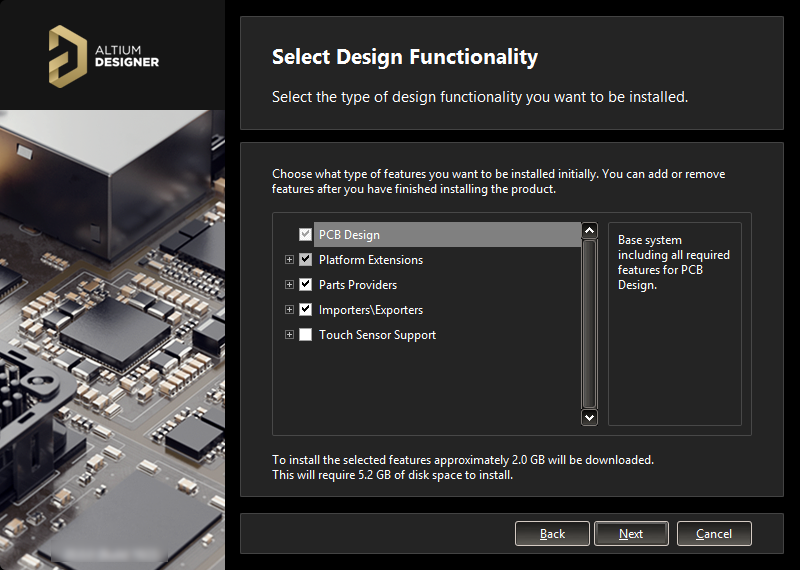
It may be a good idea to setup a separate design rule for minimum clearance between polygon pours and trackspads for example 08mm to make it. Including a schematic PCB module and an auto-router and differential pair routing features it supports track length tuning and 3D modeling. Altium decides how to apply design rules by evaluating one or more queries. Change the minimum clearance value accordingly. Installing Altium Designer Altium Designer 20 0 User Manual Documentation.
 Source: pinterest.com
Key highlights New PCB connection drawing options New options have been implemented in the View Configurations dialog for Show All Connections In Single Layer Mode and Use Layer Colors For Connection Drawing. Satisfying these requirements requires understanding and consistency throughout the entire design process. Users must have an Altium Account created by ITS. Start Your Free Trial. Pin On Thesecrack Com.
 Source: altium.com
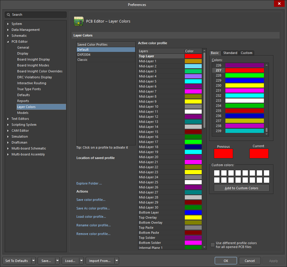
Altium Designer includes tools for all circuit. Rigid-Flex Board Planning Mode. Ad Easy Modern And Powerful PCB Design. It may be a good idea to setup a separate design rule for minimum clearance between polygon pours and trackspads for example 08mm to make it. Defining Pcb Editor Layer Color Preferences For Altium Designer Altium Designer 21 User Manual Documentation.
 Source: sk.pinterest.com
Key highlights New PCB connection drawing options New options have been implemented in the View Configurations dialog for Show All Connections In Single Layer Mode and Use Layer Colors For Connection Drawing. Altium Designer PCB library - Footprints Schematic Symbols 3D models for Altium Designer - FREE to download. In the case of the electrical clearance rule two queries are executed. The rule identifies the closest points on the targeted nets and checks the distance between them in the X-Y and Z planes. Pin On Software Provider.
 Source: altium.com
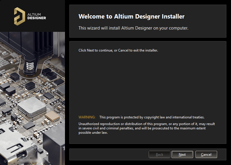
Altium decides how to apply design rules by evaluating one or more queries. In the case of the electrical clearance rule two queries are executed. Key highlights New PCB connection drawing options New options have been implemented in the View Configurations dialog for Show All Connections In Single Layer Mode and Use Layer Colors For Connection Drawing. Now in this board design only one of the inner layers is being used for 750 volt routes. Installing Altium Designer Altium Designer 19 1 User Manual Documentation.
 Source: altium.com
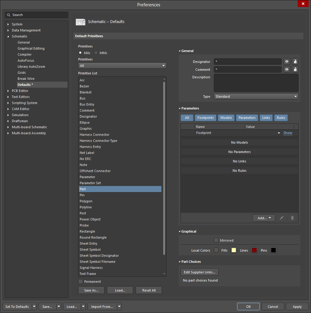
8 Generate PCB Production documentation Assembly Drawings Schematic in PDF format etc 9 Create 3D Model of PCB. Key highlights New PCB connection drawing options New options have been implemented in the View Configurations dialog for Show All Connections In Single Layer Mode and Use Layer Colors For Connection Drawing. Now in this board design only one of the inner layers is being used for 750 volt routes. This Paper Explores the Advantages to using Net Ties in Altium Designer to Join Multiple Nets shorts Into One Single Net at Very specific Locations in the PCB. Configuring Schematic Part Object Properties In Altium Designer Altium Designer 21 User Manual Documentation.
 Source: altium.com
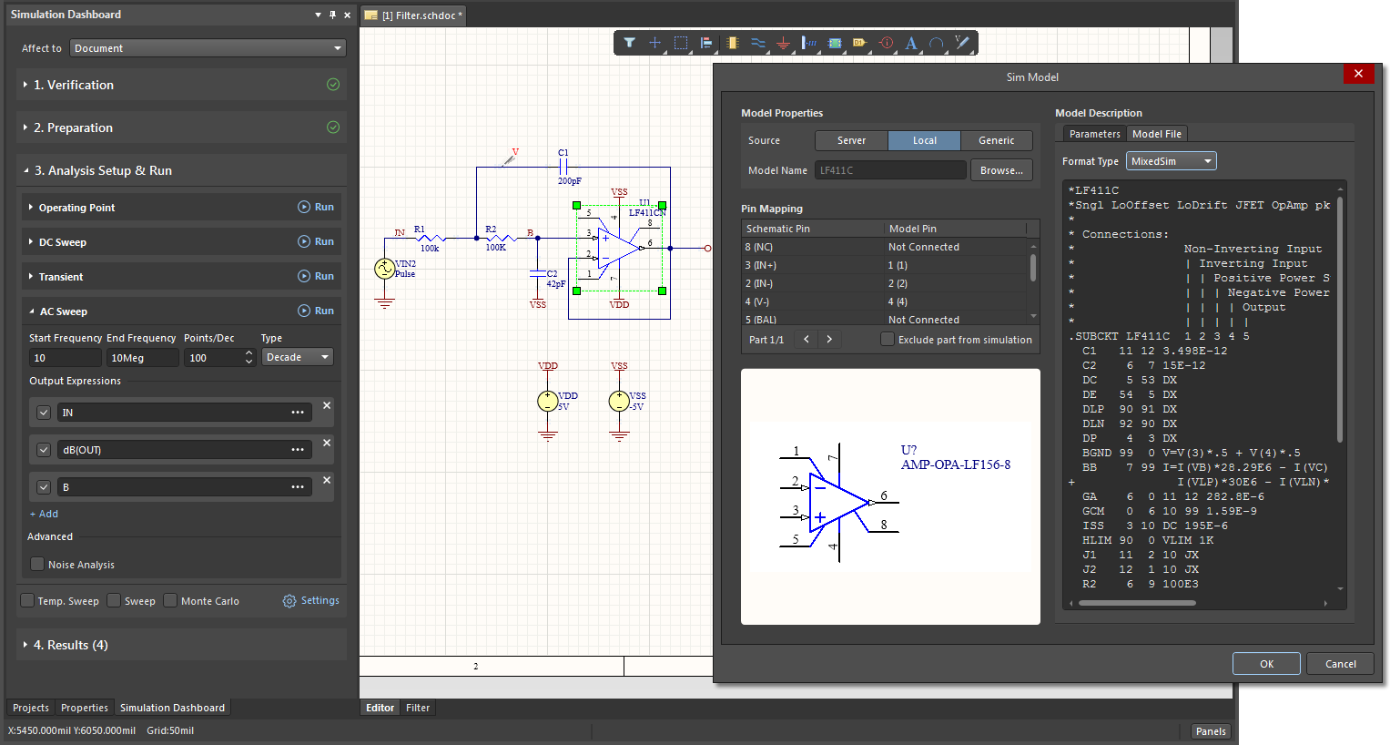
New in Altium Designer 21. Rules in Altium Designer are presented in the form of a hierarchy - from the fundamental rules covering the entire board to the rules of individual net classes. Altium decides how to apply design rules by evaluating one or more queries. The rule identifies the closest points on the targeted nets and checks the distance between them in the X-Y and Z planes. Nfs 21 0simulation Interface Updates Ad Altium Designer 21 User Manual Documentation.
 Source: altium.com
Easy to Start Simulations. Contact ITS to request an Altium Account. About Press Copyright Contact us Creators Advertise Developers Terms Privacy Policy Safety How YouTube works Test new features Press Copyright Contact us Creators. If you are interested all the design documentation and Gerbers files produce in this course can be used to build your own PCB. Replace Component Managed Altium Designer 21 User Manual Documentation.
 Source: altium.com
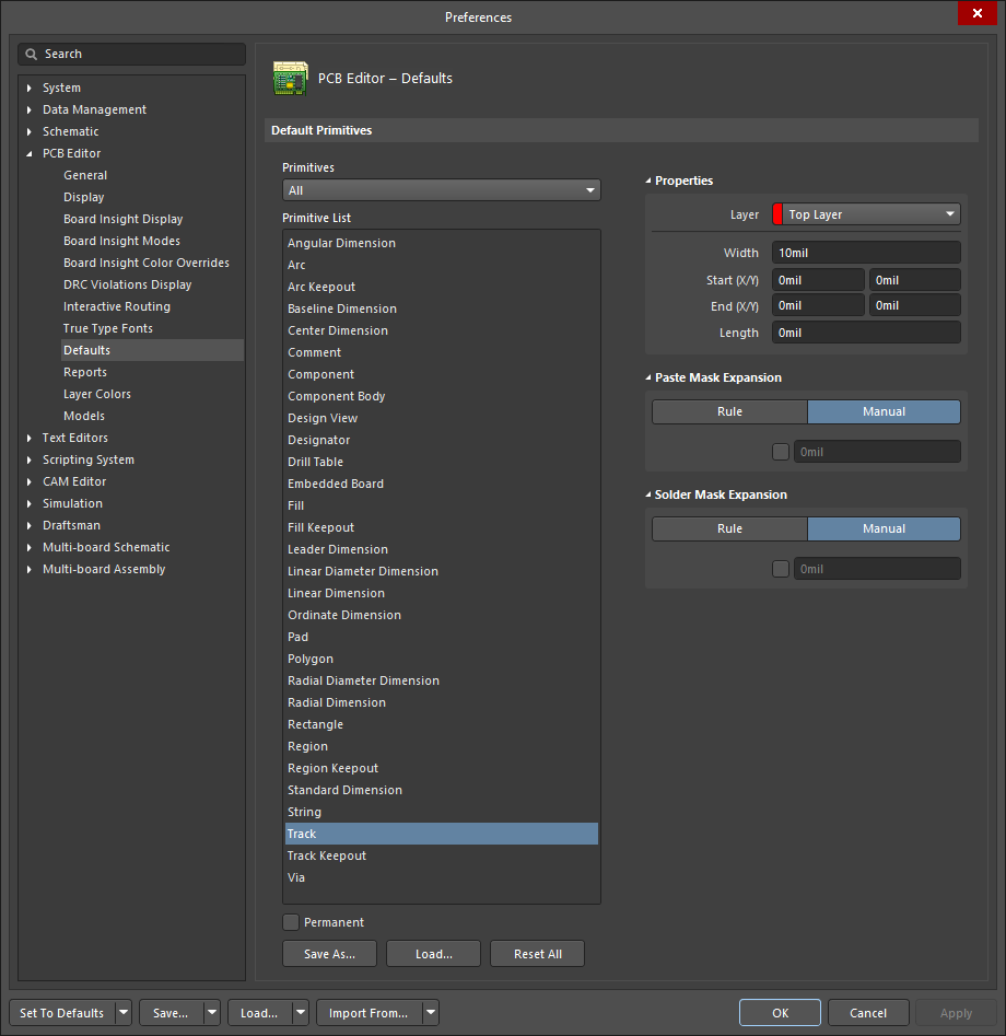
8 Generate PCB Production documentation Assembly Drawings Schematic in PDF format etc 9 Create 3D Model of PCB. Users must have an Altium Account created by ITS. The Net Tie is a Component Type that allows PCB Engineers and Designers flexibility when Handling a Variety of Design Challenges. 0133 Dec 28 2020. Configuring Pcb Track Object Properties In Altium Designer Altium Designer 21 User Manual Documentation.
 Source: thehouseofportable.com
Comprehensive Simulation Model Support. First Object query is InNetClass 750Volts And OnMid. Pushing The Boundaries Of Whats Possible. Key highlights New PCB connection drawing options New options have been implemented in the View Configurations dialog for Show All Connections In Single Layer Mode and Use Layer Colors For Connection Drawing. Altium Designer 20 0 12 Portable Setup The House Of Portable.


