Active filters have. Active techniques can also reduce the cost of capacitor in EMI filters by enhancing the performance of low cost capacitors. Active filter design techniques.
Active Filter Design Techniques, The unity-gain Sallen-Key inherently has the best gain accuracy because its gain is not dependent on component values. Active Low-Pass Filter Design 3 The choice of circuit topology depends on performance requirements. This twopart paper presents a representative sample of recent advances in microwave active filter design.
 Notch Filters An Overview Sciencedirect Topics From sciencedirect.com
In the second part we discuss design techniques for tunable structures and frequency control. Active techniques can also reduce the cost of capacitor in EMI filters by enhancing the performance of low cost capacitors. This twopart paper presents a representative sample of recent advances in microwave active filter design. First we present switchable and continuouslytunable bandstop filters employing MMIC negative resistances to compensate for losses.
In Step 1 the response of the filter is determined meaning the attenuation andor phase response of the filter is defined.
Analog filter design. Howard Austerlitz in Data Acquisition Techniques Using PCs Second Edition 2003. The unity-gain Sallen-Key inherently has the best gain accuracy because its gain is not dependent on component values. Transformations are then applied to convert the prototype. This plot will allow for a determination of the range of frequencies for which an op-amp circuit operates optimally. Filter circuits are used in a wide variety of applications.
Read another article:
 Source: sciencedirect.com
First Online 16 April 2019. This paper describes a design technique for designing wideband RF filters and illustrates this with the design of a 5 resonator filter with a. Refer to Chapter 6 in the. Input and output impedance buffering and provides for greater flexibility for the design of the frequency response. Active Filters An Overview Sciencedirect Topics.
 Source: sciencedirect.com
This paper describes a design technique for designing wideband RF filters and illustrates this with the design of a 5 resonator filter with a. This plot will allow for a determination of the range of frequencies for which an op-amp circuit operates optimally. Transformations are then applied to convert the prototype. Active Filter Circuits Example. Active Power Filter An Overview Sciencedirect Topics.
 Source: nutsvolts.com
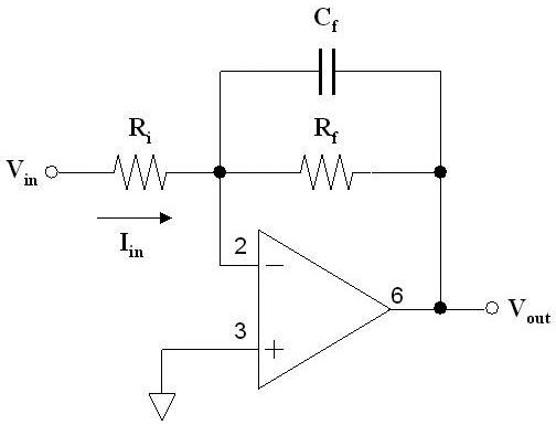
Refer to Chapter 6 in the. 16-1 Active Filter Design Techniques inproceedingsKugelstadt2001161AF title16-1 Active Filter Design Techniques authorThomas Kugelstadt year2001. Design a band-pass filter for a graphical equalizer that has gain 2 within the frequency between 100 and 10000 Hz. The simplest design of a bandpass filter is the connection of a high pass filter and a low pass filter in series which is commonly done in wideband filter applications. Filter Basics Stop Block And Roll Off Nuts Volts Magazine.
 Source: analog.com
It is also possible to construct filters with just capacitors and amplifiers so-called switched capacitor filters but we will restrict our experiment to the conventional active filter with resistors capacitors and. Howard Austerlitz in Data Acquisition Techniques Using PCs Second Edition 2003. In the second part we discuss design techniques for tunable structures and frequency control. This twopart paper presents a representative sample of recent advances in microwave active filter design. Why Does Voltage Reference Noise Matter Analog Devices.
 Source: bndhep.net
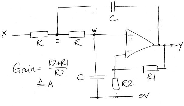
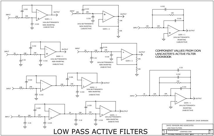
Positive negativeor only positive single supply The frequencies that need to be passed and those that need to be rejected. The unity-gain Sallen-Key inherently has the best gain accuracy because its gain is not dependent on component values. Design a band-pass filter for a graphical equalizer that has gain 2 within the frequency between 100 and 10000 Hz. This twopart paper presents a representative sample of recent advances in microwave active filter design. Filter Design Guide.
 Source: bndhep.net
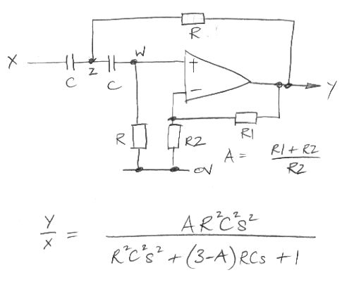
First we present switchable and continuouslytunable bandstop filters employing MMIC negative resistances to compensate for losses. The MFB is generally preferred because it has better sensitivity to component variations and better high-frequency behavior. Refer to Chapter 6 in the. In Step 2 the topology of the filterhow it is builtis defined. Filter Design Guide.
 Source: bndhep.net
This twopart paper presents a representative sample of recent advances in microwave active filter design. Publisher Name Springer Cham. More work will be required to further. View ET332_W2Assignmentdocx from EET 209 at Pennsylvania College Of Technology. Filter Design Guide.
 Source: electrical4u.com
What is the Splicing of Optical Fibers. In the field of telecommunication. While improving out-of-band linearity and reducing active area. We then generalise the principle to the active-impedance profile AIP technique which is illustrated with the application to multistandard and pseudomultipole filters. Band Pass Filter What Is It Circuit Design Transfer Function Electrical4u.
 Source: circuitstoday.com
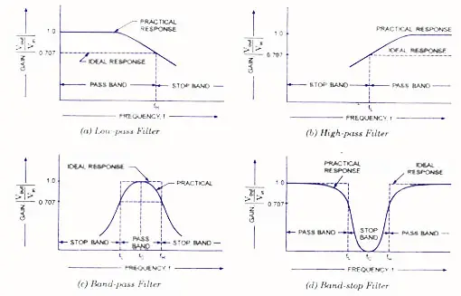
Positive negativeor only positive single supply The frequencies that need to be passed and those that need to be rejected. Thus a first order high pass filter and a first order low pass provide a second order bandpass while a second order high pass filter and a second order low pass result in a fourth order bandpass response. Amplifiers are used in filters for designing to enhance the predictability and performance. To design a filter four things must be known in advance. Classification Of Active Filters.
 Source: sciencedirect.com
While improving out-of-band linearity and reducing active area. Active Filter Design Techniques Thomas Kugelstadt 161 Introduction What is a filter. Initial evaluation has demonstrated the feasibility of this approach. This plot will allow for a determination of the range of frequencies for which an op-amp circuit operates optimally. Notch Filters An Overview Sciencedirect Topics.
 Source: swarthmore.edu
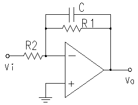
Amplifiers are used in filters for designing to enhance the predictability and performance. While improving out-of-band linearity and reducing active area. Design Techniques for Continuous-Time ΔΣ Modulators With Embedded Active Filtering Abstract. Every data acquisition systems need them for bandwidth-limiting signals before ADCs as anti-aliasing filters or after DACs as anti-imaging filters. Introduction To Filters.
 Source: electronicshub.org
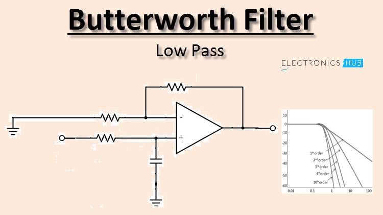
Input and output impedance buffering and provides for greater flexibility for the design of the frequency response. Analog Circuit Theory and Filter Design in the Digital World. The online tutorials include fundamental design techniques for analog design fundamentals. This paper describes a design technique for designing wideband RF filters and illustrates this with the design of a 5 resonator filter with a. Low Pass Butterworth Filter Circuit Design And Applications.
 Source: swarthmore.edu
First Online 16 April 2019. Analog Circuit Theory and Filter Design in the Digital World. We then generalise the principle to the active-impedance profile AIP technique which is illustrated with the application to multistandard and pseudomultipole filters. This plot will allow for a determination of the range of frequencies for which an op-amp circuit operates optimally. Introduction To Filters.
 Source: sciencedirect.com
Publisher Name Springer Cham. Positive negativeor only positive single supply The frequencies that need to be passed and those that need to be rejected. While improving out-of-band linearity and reducing active area. The simplest design of a bandpass filter is the connection of a high pass filter and a low pass filter in series which is commonly done in wideband filter applications. Active Filters An Overview Sciencedirect Topics.
 Source: bndhep.net
First we present switchable and continuouslytunable bandstop filters employing MMIC negative resistances to compensate for losses. Filter circuits are used in a wide variety of applications. However having the filter inside a ΔΣ loop can be problematic with respect to stability. Precision DAC Video Tutorials. Filter Design Guide.

